.jpg) |
| Science Museum, London INV-1862-89 |
Science Museum,
Exhibition Road, South Kensington, London SW7
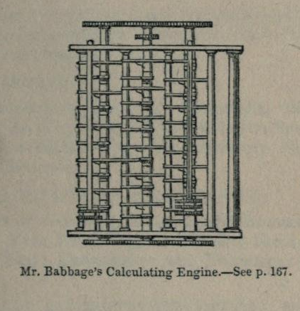
Portion or Fragment of the Difference Engine put together in 1832. It is the most important of the fragments to have survived. It was assembled by Clement for Babbage as a test piece to illustrate the actions of the calculating part of DE1. It comprises of 18 figure wheels arranged in three columns; a special driving mechanism was developed for it. It contains just under 2000 components.
Following cancellation of the DE1 project it was transferred by the Government to the King's College Museum, London in 1843, where it remained for 29 years. In 1862 it was placed on show at International Exhibition held that year. Subsequent to that it was lent to the Science Museum by the Board of Trade. INV-1862-89.
There is a replica of this model in the Smithsonian Institution, Washington made in 1957 by Munro Ltd for IBM.
Driving Mechanisms

Notes and References
This was the Portion or Fragment of the Difference Engine put together by Joseph Clement in 1832 and delivered by him to Babbage's home in Dorset Street late that year
Benjamin Herschel Babbage, Babbage's eldest son, produced a pamphlet called Babbage's Calculating Machine, 28th September 1872 on how to operate the above fragment or model of the Difference Engine. Reproduced here:
Marshall's paper (1873) reproduced here:
Babbage's Calculating Machine,
This account refers partly to the production of this model engine
Charles Babbage's First Difference Engine- Account 1
These photos were made from this trial model during the repair after an accident with this machine at the Science Museum in London
Replica in Smithsonian Museum, Washington
http://americanhistory.si.edu/collections/search/object/nmah_904254

Science Museum Library
17 Technical Drawings of the replica of the Fragment of the First Difference Engine (1832) drawn by J.W. Harding of Munro Ltd, London N11 in 1957 for IBM. Science Museum Library reference no. M.S.P. 19.
Drg 1 Bolting Arms and Index Arms drawn 1.7.1957
Drg 2 Adding Wheel and Locking Mechanisms drawn 2.1.1957
Drg 3 Bolting and Carrying Mechanisms drawn 15.7.1957
Drg 4 Plan sectional view drawn 28.6.1957
Drg 5 Framing Plates and spacers drawn 19.7.1957
Drg 6 Miscellaneous parts drawn 25.7.1957
Drg 7 Alarm mechanisms drawn 7.8.1957
Drg 8 'Eating one's own tail' Mechanisms drawn 9.8.1957
Drg 9 Plan, side view and elevation view of top and driving mechanisms drawn 10.8.1957
Drg 10 Top Framing Plate drawn 26.8.1957
Drg 11 Driving Gear drawn 6.9.1957
Drg 12 Driving Gears drawn 10.9.1957
Drg 13 Shafts drawn 12.9.1957
Drg 14 Bottom Framing Plate drawn 12.9.1957
Drg 15 Springs and Spring Cases drawn 14.9.1957
Drg 16 Miscellaneous Parts drawn 16.9.1957
Drg 16a Carry Lever Springs drawn 7.1.1957
Total number of parts in replica: 1976
Henry Mills Alden (1865). Harper's New Monthly Magazine. Volume 30 No. 175. Harper & Brothers. pp. 34–.
No comments:
Post a Comment